Xavier
Installation
System Requirements
- Windows XP or newer
- Python 3.5 with numpy, pandas, and matplotlib libraries
Tip
Download Anaconda Python 3.5 Distribution , which has all of the required libraries included
Download Instructions
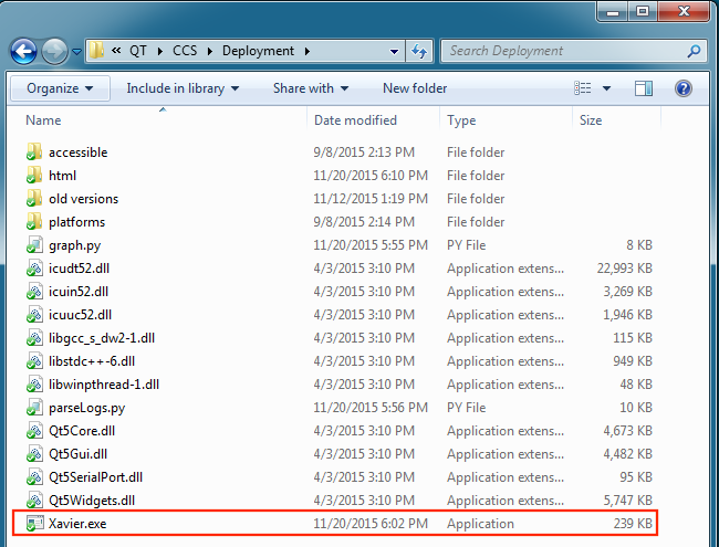
- Download and unzip
Xavier Deployment Folder - Open up Xavier.exe
- Setup a default directory that data will be saved to
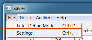
Settings
Access Xavier Settings by navigating to File->Settings.. or by pressing Ctrl + ,
Note
Settings cannot be changed in the middle of a session
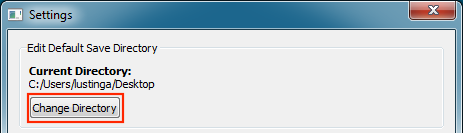
Edit Default Save Directory
- Click
Change Directoryto setup a new save location.
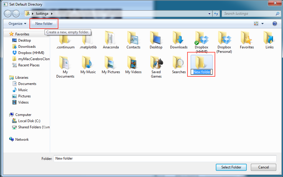
- Navigate to an existing folder or create a new folder for future data.
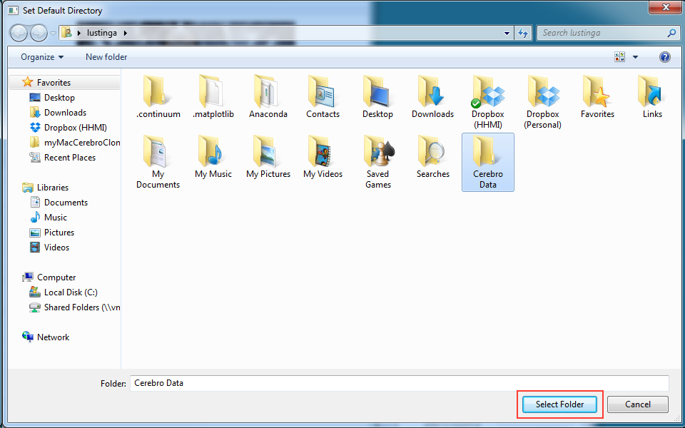
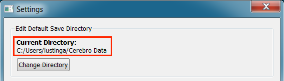
- Finally, click Select Folder. The “Current Directory” will reflect updated save path
Edit Session Setup Lists
Labeling COM Ports
When multiple usb devices are connected to the computer, it can be hard to keep track of which COM Port belongs to which device. To minimize confusion when connecting to serial ports, Xavier allows you to label COM Ports.
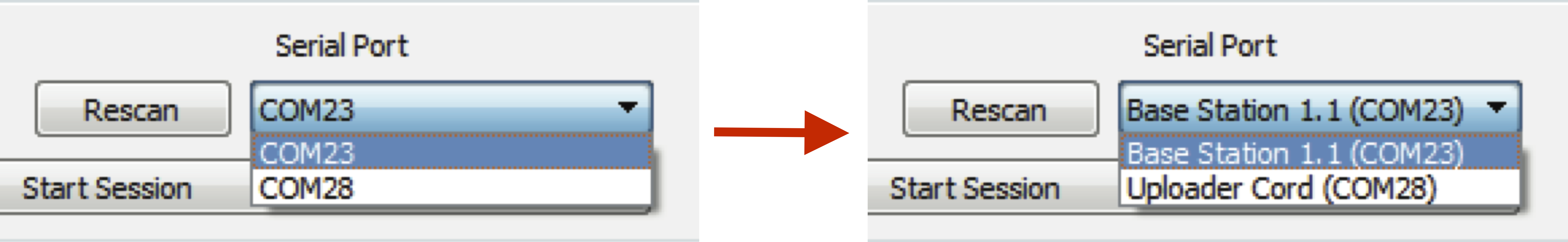
Adding Labels
- From the dropdown box, select the COM Port you want to add a label to
- Type the new label into the textbox and click
Add/Edit Label(or press Enter)
Editing Labels
- Double-click the labeled COM Port from the list that you want to edit. A label editing dialog will appear.
- Type the new label into the textbox and click
Change Label
Removing Labels
Select the labeled COM Port from the list that you want to remove and click Remove Selected
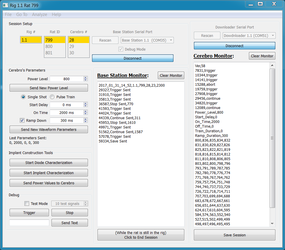
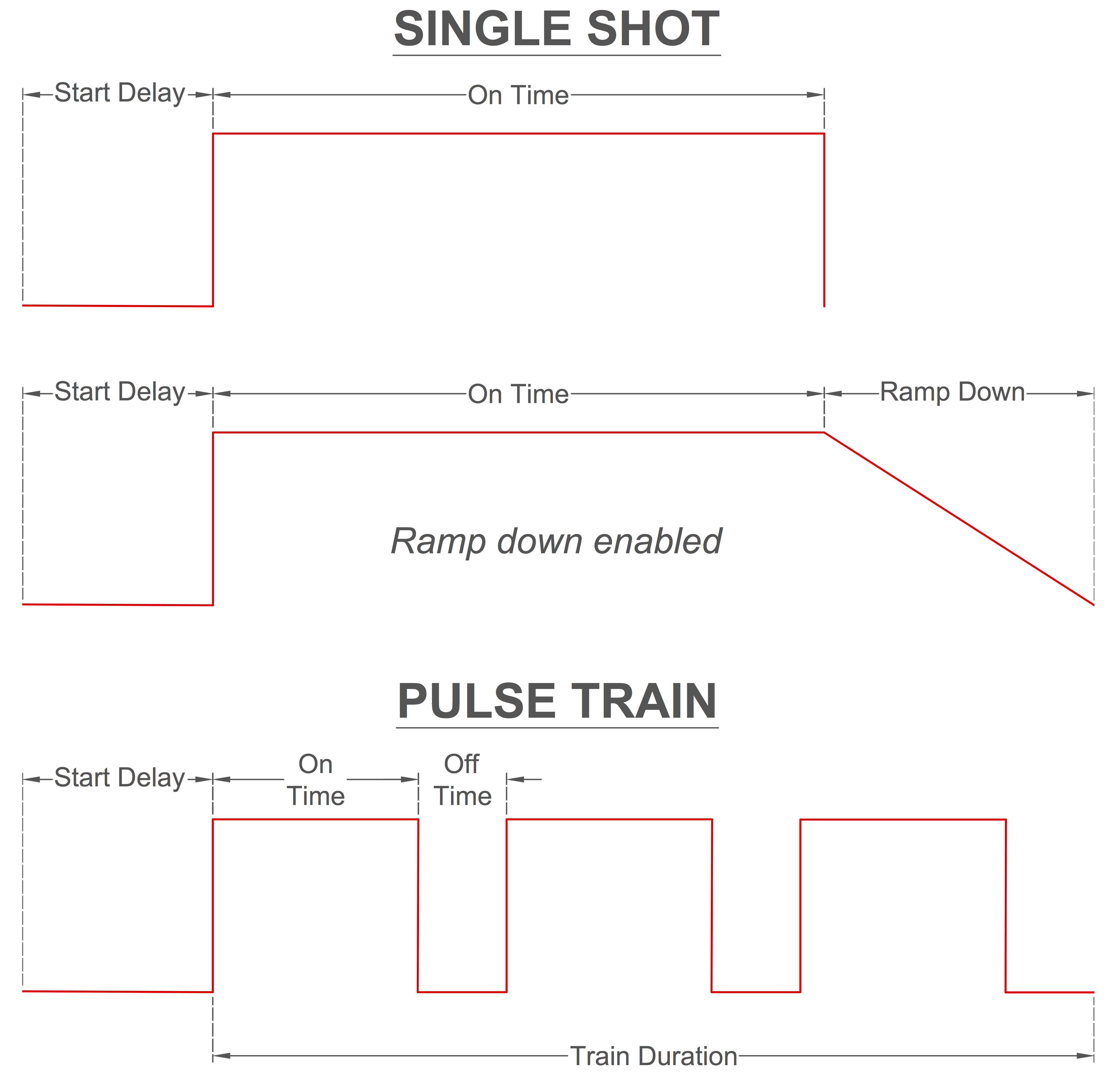
Waveform Parameters
Five waveform parameters (Start Delay, On Time, Off Time, Train Duration, Ramp Down) can be wirelessly changed throughout the session. The user can make changes using either a Single Shot mode with an optional ramp down or Pulse Train mode. Non-applicable parameters are automatically set to zero depending on options selected. Once the parameters are sent to and received by Cerebro, they are saved to non-volatile memory and are therefore retained between sessions.
Checking Current Parameters
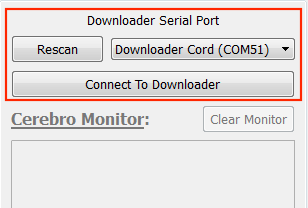
- Select the appropriate Downloader Serial Port and click
Connect to Downloader
- With Cerebro turned off, plug the Downloader Cord into Cerebro’s micro usb port
- Turn on Cerebro.
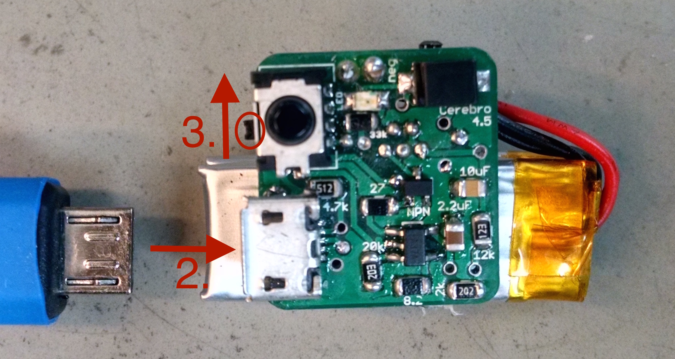
- A dialog box with all of Cerebro’s parameters will appear. Additionally, the “Cerebro’s Parameters” section will automatically be updated to match the parameters currently on Cerebro.

Changing Parameters
- In the “Cerebro’s Waveform Parameters” section, select desired pulse options and modify the parameters
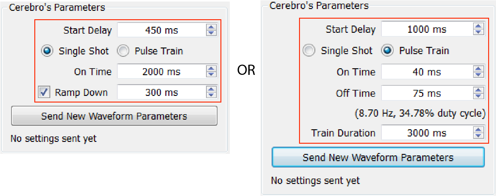
- Click
Send New Waveform Parameters. - A confirmation dialog will appear.
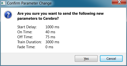
- Once confirmed, the settings will be sent and the last sent parameters will be displayed at the bottom

See also
The IR Remote can be used as an alternative to send new parameters. Additionally, it is capable of checking the current parameters saved to Cerebro’s memory.
Implant Construction Tools
Diode Characterization
Implant Characterization
Send Power Values to Cerebro
Each implant has different response curves to power levels provided by Cerebro. To output a desired light level, Cerebro must know how much current to provide. To implement a fade, Cerebro must know multiple current levels to step through such that the implant’s light output linearly decreases from a desired light output down to 0 mW. We therefore send Cerebro a vector of values that correspond to our desired light output with a linear fade to 0 mW.
- Select “Debug Mode” and start a new session.
- In the “Implant Construction Tools” section click
Send Power Values to Cerebro - Assuming you’ve previously characterized an implant, click
Create fade vector from power meter file - Input a target power into the text box and then click
Select Power Meter File - After choosing a file, a implant characterization graph will appear, a summary file will be saved to the same directory as the selected power meter file.
- The fade vector is automatically copied from the summary file into the fade vector input.
- Fill in the the information for Cerebro # and implant # then click
Send Values - Confirm you want to send new power levels to Cerbro and the values will be sent.
Running an Experiment
Starting a New Session
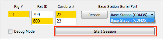
- Fill out experimental setup information.
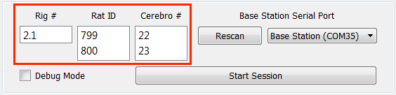
- Select a Base Station Serial Port.

- Click
Start Session
Ending a Session and Saving Data
Important
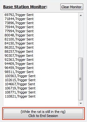
- Before opening the rig and removing the rat, click the
End Sessionbutton. “Save Sent” will be printed to the Base Station Monitor.
- Turn off Cerebro and disconnect it from the rat’s head implant
- Make sure the Downloader Cord is plugged into the computer
- Select the appropriate Serial Port and click
Connect to Downloader

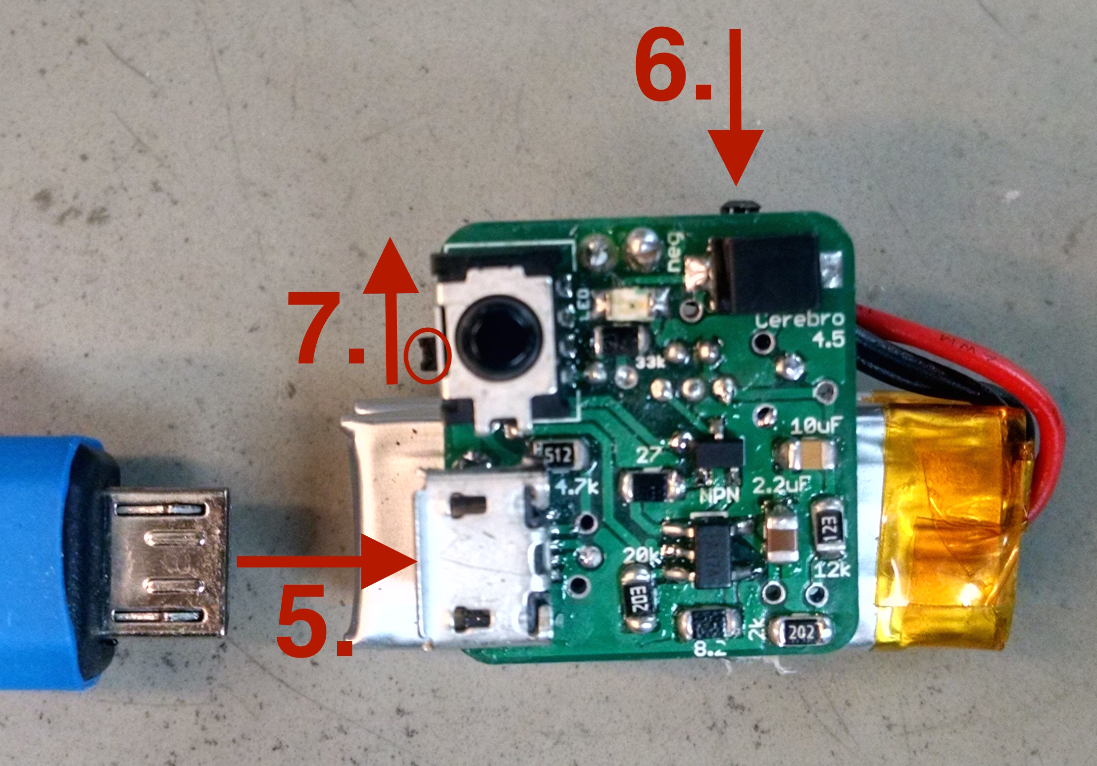
- Plug the Downloader Cord into Cerebro’s micro usb port
- Press and hold the download button
- While still holding down the download button, switch Cerebro on. The event log will be printed to the Download Monitor. You may release the download button once events have begun being printed to the Cerebro Monitor.
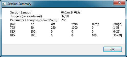
- Click
Save Sessionbutton.
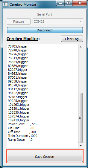
- After saving, a dialog will appear with a summary of the session