IR Remote
Required Tools
Bill of Materials
Tip
The pins on the vertical USB plug are very short and fail to protrude from standard thickness (~1.6mm) PCBS. Therefore I recommend ordering thinner boards (~0.8mm) to make soldering the connector easier.
| Qty | Description | Datasheet | Vendor |
|---|---|---|---|
| 1 | IR Remote PCB | OSH Park | |
| 1 | Rotary encoder | A14-LC-TT |
Sparkfun |
| 1 | OLED display | Adafruit | |
| 1 | ATmega328 | ATMEGA328P-AU |
Octopart |
| 1 | 16 MHz Resonator | CSTLS16M0X53-A0 |
|
| 1 | Male micro USB vertical plug | ZX20-B-5S |
|
| 1 | Male micro USB shielding | ZX20-B-SLDC |
|
| 1 | Female micro USB horizontal socket | 10118193-0001LF |
|
| 1 | Toggle switch | ATE1D-2M3-10-Z |
|
| 1 | IR LED | OED-EL-1L2 |
|
| 1 | JST battery connector | S2B-PH-K-S(LF)(SN) |
Design Files
Build Instructions
Uploading Firmware
Attention
If you have not yet setup the Arduino environment or the Cerebro Utility Shield, refer to Setting up Arduino IDE and/or Setting up Utility Shield before moving on.
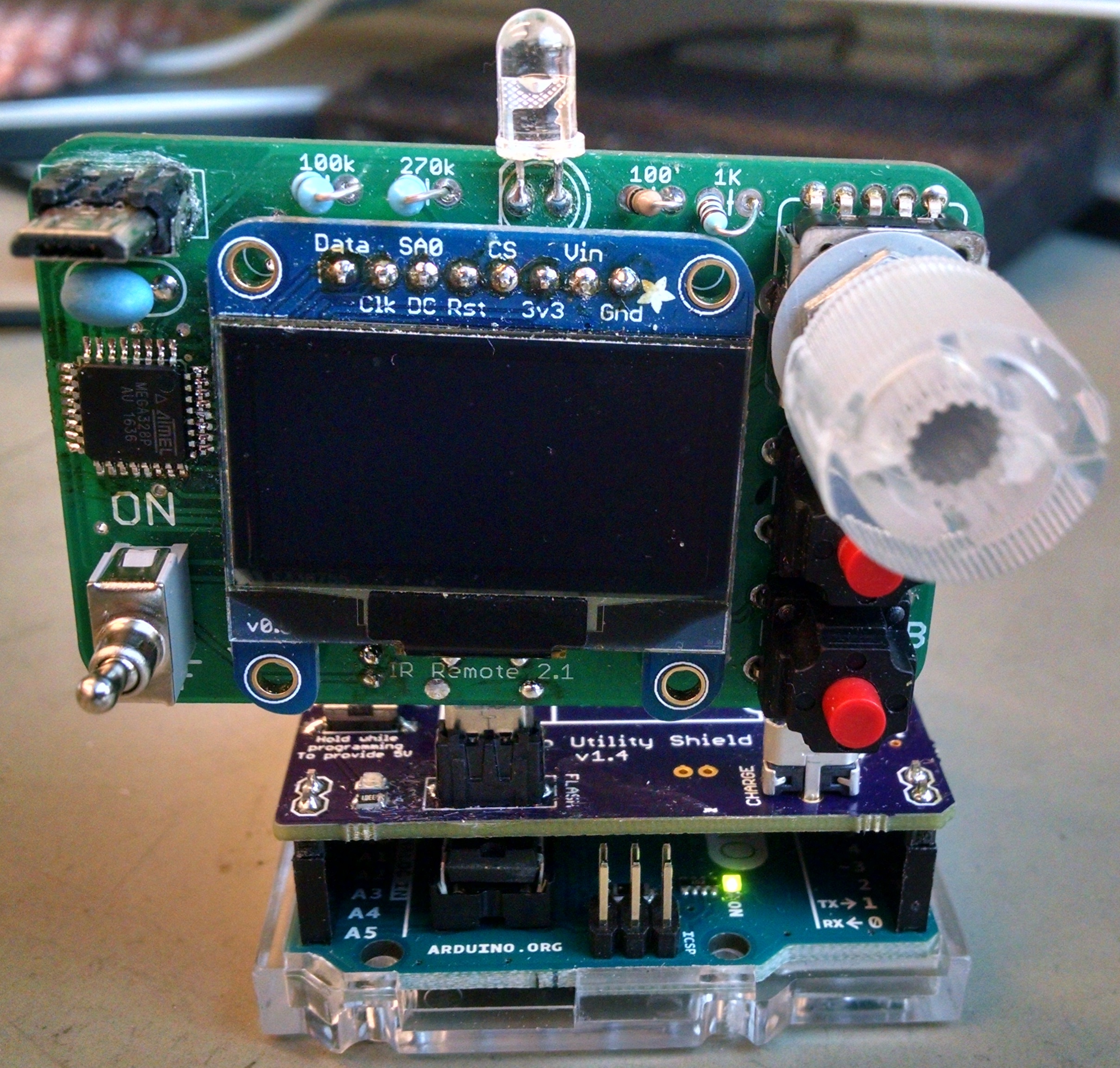
- With the battery connected, switch the remote on
- Plug the remote into the Utility Shield via the micro usb connection
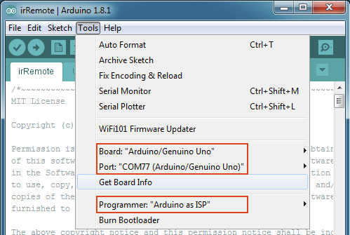
- Open up the Arduino application and make the following selections under the Tools menu:
Board: “Arduino/Genuino Uno”
Port: “COMXX (Arduino/Genuino Uno)”
Programmer: “Arduino as ISP”
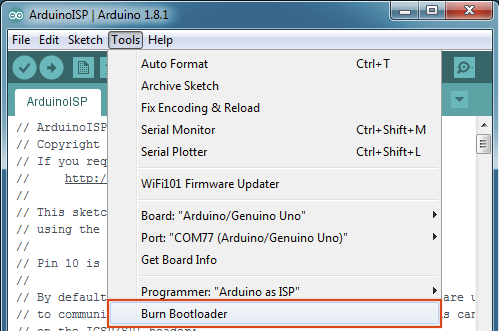
- Burn the bootloader by selecting Tools -> Burn Bootloader
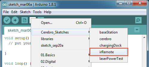
- Select the firmware that will be uploaded onto the IR Remote File -> Sketchbook -> Cerebro Sketches -> irRemote
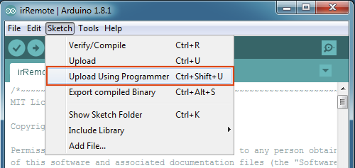
- Upload the firmware by selecting Sketch –> Upload Using Programmer
User Guide
Demonstration Video
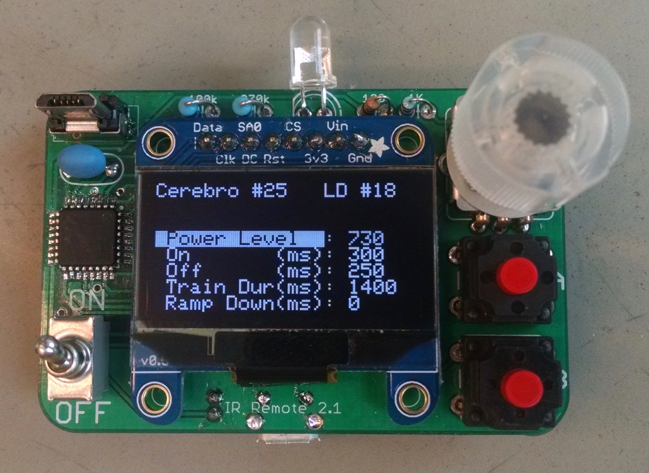
Checking Cerebro’s Waveform Parameters
- Turn on the IR Remote
- With Cerebro turned off, plug it into the IR Remote
- Switch on Cerebro. The current waveform parameters as well as the battery voltage will be displayed.
Editing and Sending Waveform Parameters
- Use the rotary knob to highlight the parameter that you would like to edit
- Click down the rotary knob to begin editing the parameters
- Rotate the knob to make coarse adjustments (clockwise to increase, counterclockwise to decrease)
- Press, hold and rotate to make fine adjustments.
- Click the rotary knob again to return to highlighting parameters
- When finished editing, Press and hold the “B” button to send the new parameters to Cerebro. The display will show “Parameters Sent”
Triggering a light pulse
- Press and release the “A” button. The display will show “Trigger Sent”
Stopping a light pulse
- Press and release the “B” button. The display will show “Stop Sent”
Starting a Calibration Routine
- Press and hold the “A” button. The display will show “Calibrate Sent”
- The yellow light on Cerebro will turn on, indicating that it has begun its calibration routine