Cerebro
Specifications
| Parameter | Test Condition | Value | Unit |
|---|---|---|---|
| Weight | 13.2 | g | |
| Dimensions | Receiver | 0.68 x 0.74 x 0.062 | in |
| Implant | 1.05 x 0.40 x 0.75 | in | |
Battery Life |
520nm, 8mW 3s pulse, 6 pulses/min | 4.25 (1700) | hours (pulses) |
| Recharge time | 1 | hour | |
| Light Wavelength | HL63603TG (Red) |
638 | nm |
PLT5 520 (Green) |
520 | nm | |
| Memory | 8192 | bytes | |
Trigger Latency |
3.06 ± 0.05 | ms | |
| Rise Time | 40 ± 10 | ms | |
| Fiber Diameter | 200 | μm | |
| Light Output (per fiber) | 520 nm diode coupled to 200 μm fiber | 0 to 15 ± 0.5 | mW |
| Input Voltage | 2.7 to 4.2 | V | |
| Idle Current | 11 | mA | |
| Peak Current | Green Laser | 370 | mA |
Bill of Materials
Tip
The pins on the vertical USB plug are very short and fail to protrude from standard thickness (~1.6mm) PCB. Therefore I recommend ordering thinner boards (~0.8mm) to make soldering the connector easier.
Caution
The Adafruit battery linked below has been confirmed to work with Cerebro. Other Li-poly batteries may be used to accommodate different weight or session length constraints, just make sure the battery capacity and C rating are capable of handling a peak current of 350 mA.
| Qty | Description | Datasheet | Vendor |
|---|---|---|---|
| 1 | Cerebro PCB | OSH Park | |
| 2 | 105 mAh Battery | 1570 |
Adafruit |
| 1 | Microcontroller | ATTINY84-20SSU |
Octopart |
| 1 | IR Sensor | TSOP6138TR |
|
| 1 | DAC (12-Bit) | LTC2630ACSC6-LZ12 |
|
| 1 | EEPROM IC (64K) | FT24C64A-ULR-T |
|
| 1 | Op Amp | OPA237NA/3K |
|
| 1 | NPN Transistor | FJX3904TF |
|
| 1 | Boost Converter | MIC2288YD5 TR |
|
| 1 | Slide Switch | AYZ0102AGRLC |
|
| 1 | Momentary Button | B3U-1000P |
|
| 1 | Male micro USB vertical plug | ZX20-B-5S-UNIT(30) |
|
| 1 | Male micro USB shielding | ZX20-B-SLDC |
|
| 1 | Female micro USB horizontal socket | 10118193-0001LF |
|
| 1 | Schottky Diode | MBRM140T3G |
|
| 1 | 10 μH Inductor | LQH43CN100K03L |
|
| 1 | 0603 Red LED | LTST-C191KRKT |
|
| 1 | 0603 Amber LED | LNJ437W84RA |
|
| 1 | 0603 0.1 μF Capacitor | ||
| 1 | 0603 10 μF Capacitor | ||
| 1 | 0603 2.2 μF Capacitor | ||
| 1 | 0603 6.8 Ω Resistor | ||
| 1 | 0603 27 Ω Resistor | ||
| 1 | 0603 100 Ω Resistor | ||
| 1 | 0603 2 kΩ Resistor | ||
| 2 | 0603 6.8 kΩ Resisor | ||
| 1 | 0603 12 kΩ Resistor | ||
| 3 | 0603 20 kΩ Resistor |
CAD Files
Code
Build Instructions
Required Tools
- Soldering iron
- Tweezers
- Flux pen
- Solder wick
- Wire cutters/strippers
- Crazy glue
- Hot glue gun
PCB Assembly
Uploading Firmware
Attention
If you have not yet setup the Arduino environment or the Cerebro Utility Shield, refer to Setting up Arduino IDE and/or Setting up Utility Shield before moving on.
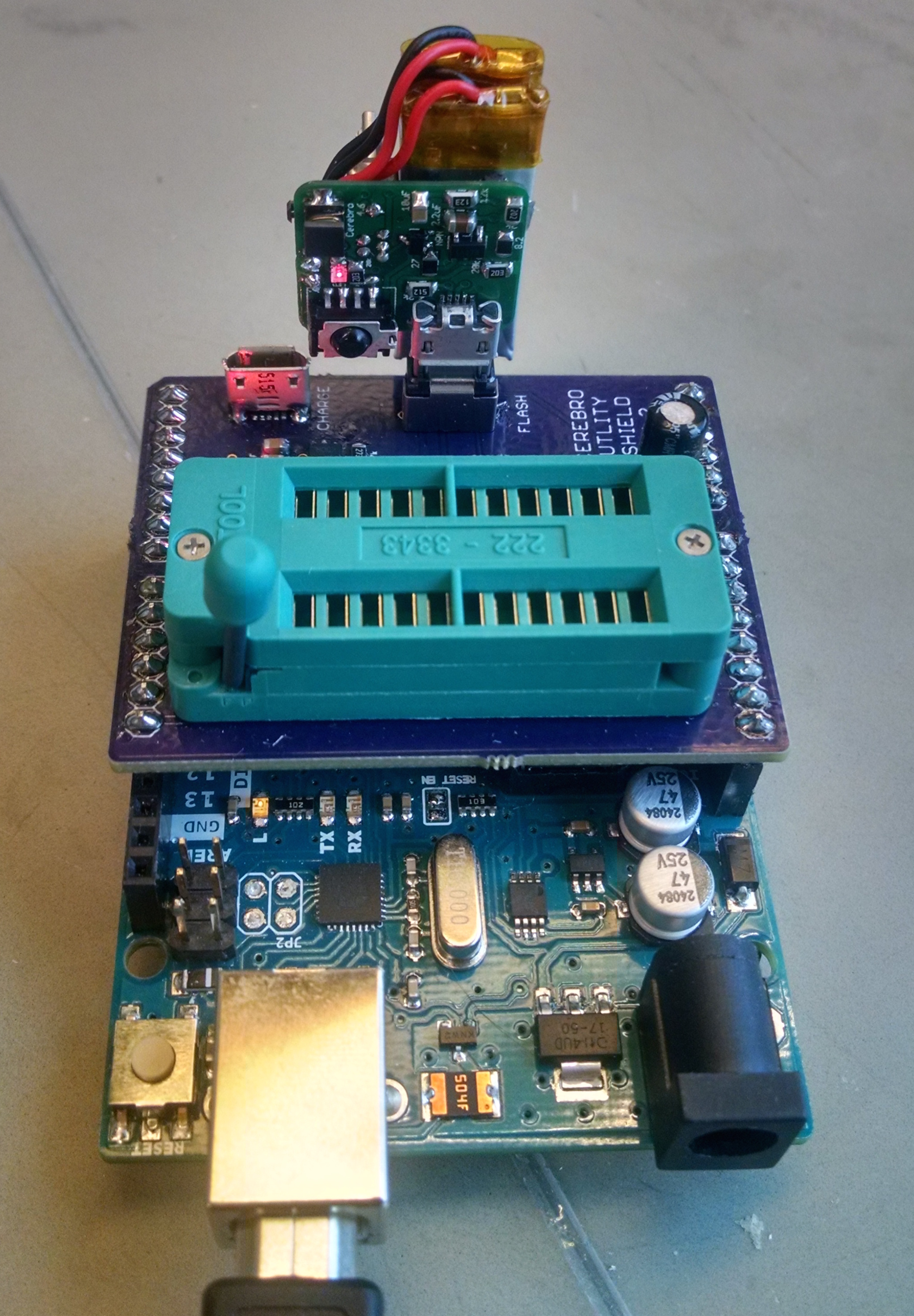
- Turn on Cerebro and plug it into the Utility Shield as shown below.
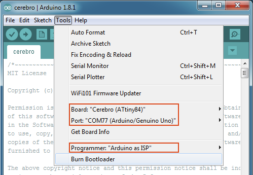
- Open up the Arduino application and make the following selections under the Tools menu:
Board: “Cerebro (ATtiny84)”
Port: “COMXX (Arduino/Genuino Uno)”
Programmer: “Arduino as ISP”
- Burn the bootloader by selecting Tools -> Burn Bootloader

- Select the firmware that will be uploaded onto Cerebro File -> Sketchbook -> Cerebro Sketches -> cerebro

- Upload the firmware by clicking the upload arrow